1. Product Introduction
Based on MTK7628 for CPU designed for nursing use scenarios a model created light weight micro-development Embedded Gateway product. DSGW-090-Caregiving have RJ45 serial portinterface, adaptable to connect to the data access of nursing beds. In addition, the gateway supports the access of BLE devices, such as health bracelets, positioning tags, bluetooth diapers and other industry equipment. Applies to Skilled Nursing, Rehabilitation Nursing, Assisted Living, Home Care, Memory Care scene. Otherwise Gateways support Openwrt system, facilitates secondary development and platform docking for customers.
| Name | Describe | Remark |
|---|---|---|
| Product Model | DSGW-090-ONDO | |
| CPU | MT7628AN | The core board is connected to the base board through patch |
| RAM | 128MB | |
| SPI Flash | 64MB | |
| Network Port | Provides UART signals for connecting to external devices, external power supply, and request signals between external devices.Nursing BedDevices communicate. | The interface definition is non-standard, and the interface is compatible with RJ45 and RJ50 crystal heads |
| USB TYPE-C | The device can be powered via TYPE-C. | This port only supplies power to the device. |
| Button | A factory reset button. | |
| Wi-Fi | Wi-Fi2.4G, 802.11b/g/n 2T2R, 300Mbps, 2 ipex antenna sockets |
This gateway uses 1T1R connection mode |
| BLE | BLE 5, 2.4G | |
| LTE | LTE Cat1, Band B2/B4/B5/B12/B13, 10 (DL)/5 (UL) |
Reserved function |
| Debug interface | Support, 1 UART interface on board | |
| SD Card and SIM Card | Reserved SD card and SIM card for LTE | The motherboard has a reserved function, but the shell does not have a reserved interface for this function |
| LED | Power status indicator light control interface | |
| Network status indicator light control interface | ||
| Control box working status indicator light control interface | ||
| Cooling Solution | Support radiator + fan | |
| Sensor Interface | Support external six-axis gyroscope sensor and magnetometer sensor | |
| LED | Flash control interface | |
| Bluetooth working status indicator light control interface | ||
| Wi-Fi working status indicator light control interface | ||
| Power Supply | Provides 17~50V DC via RJ45 or 5V/2A DC power via TYPE-C | |
| Operating Temperature | -10℃ ~ 55℃ | |
| Storage Temperature | -20℃ ~ 65 ℃ | |
| PCBA Dimensions | 81.95*89.55mm |
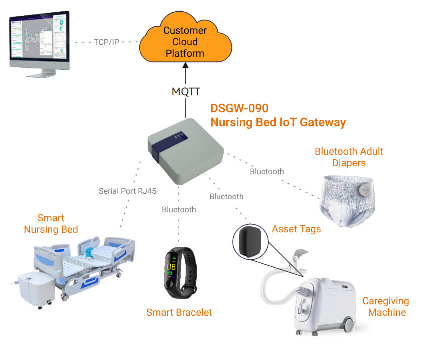
Functional description of nursing IoT scenario:
1. Vital signs monitoring, patient dataStatistics and infection detection
DSGW-090 gateway reads data through Bluetooth Wear. The data collected by the smart bracelet provides a steady stream of actionable data and verification of care, automate repetitive, labor-intensive workflows and documentation while delivering the best possible care to your patients.
2. Positioning services and nursing process monitoring
DSGW-090 obtains signal strength data from positioning tags on medical equipment such as nursing machines and smart bracelets worn by patients to track and manage important assets such as patients and durable medical equipment, and locate them when needed. Gain visibility into workflow interactions between patients, caregivers, and devices, and passively validate care plan adherence and compliance.
3. Incontinence Care Remote Monitoring
DSGW-090 gateway uses the connected smart Bluetooth diaper data toReal-time, responsive incontinence care revolutionizes caregivers’ greatest workflow burden, directly improving clinical outcomes, patient dignity, and satisfaction for families, residents, and caregivers.
1. Low efficiency of nursing staff
In addition to completing normal nursing work for patients, nursing staff also need to deal with frequent emergencies and frequent scheduled inspections, and spend more time on statistics and analysis of patient data. Dusun Nursing Gateway DSGW-090 and external devices can provide intelligent feedback on emergency situations (such as incontinence, etc.) and support background data statistics and document output, greatly improving the efficiency of nursing staff.
2. Poor standardization of nursing process
Through personnel management, it is impossible to standardize the constraints on nursing staff, resulting in poor compliance with the nursing process, which leads to some accidents. Through the Dusun Nursing Gateway and external positioning tag devices, the location trajectory of medical equipment, medical staff, and patients can be viewed in real time, so as to better carry out standardized nursing.
Dusun SDK is a highly customizable system developed based on the Openwrt system. It is used to develop nursing gateways with advantages in flexibility and scalability. It is very suitable for developing nursing gateways with high customization and security. The following is the software framework of the default Openwrt system of DSGW-090.
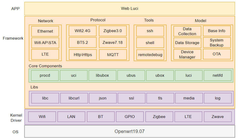
Dusun provides industry SDK source code that matches the nursing motherboard, supporting customers to conduct micro-development to achieve rapid productization.
Dusun Nursing Industry SDK has the following features:
1. Streamlined operating system:
On the premise of meeting industry applications, the number of components is streamlined, the system resource utilization rate is high, thereby reducing hardware costs, and to a certain extent, the functional structure is optimized, the system architecture is reasonably laid out, and the system is more efficient and easy to maintain;
2. BSP with industry attributes:
According to the types of peripheral devices used in the industry, driver transplantation and debugging are carried out and industry algorithms are adapted to meet the customer’s needs for selecting an overall hardware + algorithm solution. In addition, Dusun BSP driver will continue to iterate the access to peripheral devices of different brands and models.
3.Easy customization:
Allows developers to customize system kernel and user space applications according to the specific needs of the nursing gateway. This allows the nursing gateway to more accurately meet the needs of specific nursing institutions;
4.Highly scalable:
Functionality can be easily expanded by installing additional software packages. This allows the Care Gateway to be continuously upgraded over time to adapt to new technical requirements or add new features
5.Powerful network functions:
It has built-in comprehensive network functions, such as routing, bridging, DHCP server, DNS forwarding, etc. These functions are very useful for building a nursing gateway;
6.Reliability and stability:
Dusun SDK is based on OpenWrt19.07 and has been extensively tested and used. It has shown good reliability and stability in long-term operation, which is very important for nursing equipment that needs to work continuously.
| Peripherals | Model | Illustrate |
|---|---|---|
| USB | -- | 5V type-C and PoE power supply |
| Matching peripheral hardware | Model | Illustrate |
|---|---|---|
| Nursing Bed | Customer Model | Customizable docking controls for customer care beds |
| Asset Location Tags | DSBC-061 | Can be installed and positioned medical equipment |
| Bluetooth smart bracelet | DSSW-010 | Bluetooth bracelet, heart rate, etc. |
| Smart Diapers | Smardii Smart Diaper Puck | Bluetooth Protocol |
none
2. Installation Instructions
⚠️:This section describes the product packaging form (boxed/antistatic bag, etc.?), packaging size, unit weight, packing instructions, etc.
1. Describe the type of box: airplane box, top and bottom box, double-insert box, buckle bottom box, drawer box;
2. Describe the type of bag: bubble bag, flat bag, sealed bag;
3. State the weight of the complete machine (excluding accessories), with one decimal place and tolerance;
4. Describe the packing situation: how many boxes are in a box, how they are arranged, and provide illustrations.
⚠️:This section describes the factory accessories list of the product
1. Use graphic description + list to describe the factory accessories of the whole machine;
2. If necessary, explain how to use the accessories, such as how to install them, installation precautions, etc.
⚠️:This section describes the installation method and installation precautions of the product. If the product is a complete machine, use diagrams to describe the appropriate installation method and installation steps. If the product is a PCBA, describe the fixed space and air avoidance rules, radiator installation, etc.
1. Whole machine status before leaving the factory: Use graphic description + text description to explain the installation method and steps of the product, and especially emphasize precautions, etc.
2. Module status at the factory: Describe the module installation method, precautions, recommended hole opening values, etc. If necessary, we can use graphic descriptions to recommend customers to assemble the module according to the structure recommended by our company.
⚠️: Use 2D wireframes to quickly describe the product dimensions. Also provide a link to download the 3D product image.
1. Use the simplest wireframe to describe the key dimensions of the product and indicate the tolerances;
2. Integrate the product into a “part state” and provide 3D drawings (STP format).
3. Hardware Instructions
The product appearance is as follows:
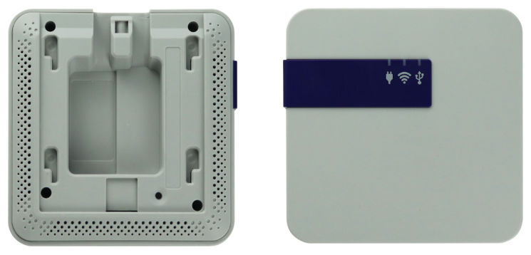
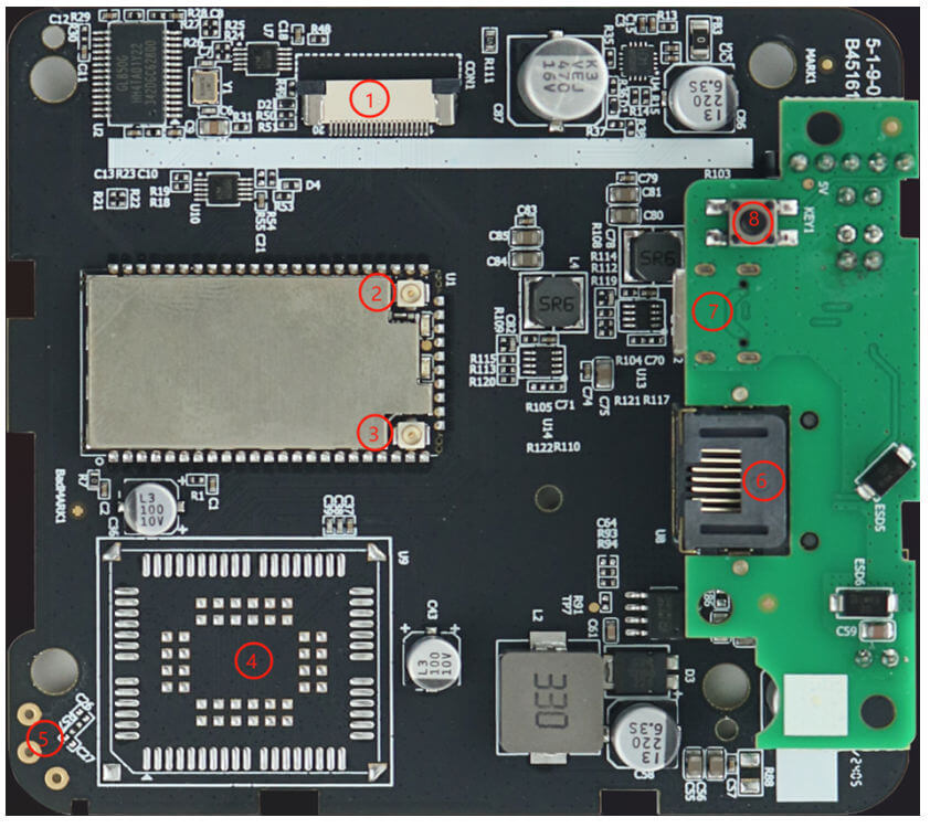
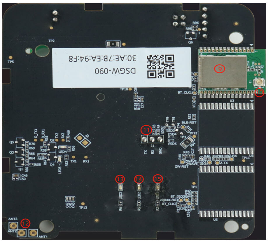
| Serial number | Describe | Remark |
|---|---|---|
| 1 | Connector between motherboard and card board | Reserve |
| 2 | WIFI module RF output port 1 | Reserve |
| 3 | WIFI module RF output port 2 | For connecting WIFI FPC antenna |
| 4 | LTE Cat1 Module | Reserved LTE module location |
| 5 | LTE Antenna Pin | Reserved for connecting LTE FPC antenna |
| 6 | RJ45 network port | Used to connect to the RJ50 terminal to provide power to the mainboard and communicate with CO61 |
| 7 | USB TYPE-C interface | Used to provide power to the motherboard |
| 8 | Button | For restoring factory settings |
| 9 | BLE Module | The module is on the mainboard and the interface is not external |
| 10 | BLE module ipex socket | Used to connect BLE module and built-in FPC antenna |
| 11 | Debug serial port | For equipment debugging |
| 12 | LTE Antenna Pin | Reserved for connecting LTE FPC antenna |
| 13 | Green LED light | Control box status indicator |
| 14 | Green LED light | Network status indicator |
| 15 | Green LED light | Power indicator |
① The mainboard uses the MT7628AN core board. The position of the core board on the PCBA is shown in the figure below:
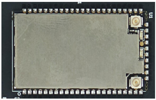
The module adopts patch mode, and its size is: 18.68*35.23mm
② The actual picture of the core board is shown below:
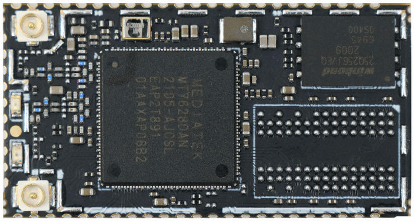
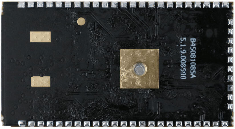
③ The U1 pin definition of the core board is as follows:
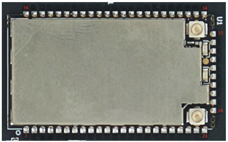
The pin function definitions are as follows:
| Serial number | Pin Name | Pin Description | IO Level | Remark |
|---|---|---|---|---|
| 1 | GND | Power Ground | 0V | Module power supply |
| 2 | VCC33 | Power positive | 3.3V | |
| 3 | VCC33 | Power positive | 3.3V | |
| 4 | GND | Power Ground | 0V | |
| 5 | SPI_CS0 | SPI device chip select 0 | 3.3V | Shared with GPIO#10 |
| 6 | REF_CLKO | Reference clock output | 3.3V | Shared with GPIO#37 |
| 7 | PREST_N | PCIe reset output | 3.3V | Shared with GPIO#36 |
| 8 | WDT_RST_N | Watchdog reset output | 3.3V | Shared with GPIO#38 |
| 9 | EPHY_LED4 | #4 Network port working indicator | 3.3V | Multiplexed with GPIO#39 function |
| 10 | EPHY_LED3 | #3 Network port working indicator | 3.3V | Shared with GPIO#40 |
| 11 | EPHY_LED2 | #2 Network port working indicator | 3.3V | Shared with GPIO#41 |
| 12 | EPHY_LED1 | #1 Network port working indicator | 3.3V | Shared with GPIO#42 |
| 13 | EPHY_LED0 | #0 Network port working indicator | 3.3V | Shared with GPIO#43 |
| 14 | PORST_N | Power-On Reset | 3.3V | Function integrated in the core board |
| 15 | UART_TXD1 | Serial port 1 signal output | 3.3V | Multiplexed with GPIO45 function |
| 16 | UART_RXD1 | Serial port 1 signal input | 3.3V | Multiplexed with GPIO46 function |
| 17 | I2S_SDI | I2S Data Input | 3.3V | Multiplexed with GPIO#0 function |
| 18 | I2S_SDO | I2S data output | 3.3V | Multiplexed with GPIO#1 function |
| 19 | I2S_WS | I2S word selection | 3.3V | Multiplexed with GPIO#2 function |
| 20 | I2S_CLK | I2S Clock | 3.3V | Multiplexed with GPIO#3 function |
| 21 | GND | Systematically | 0V | |
| 22 | ANT | Antenna signal output | Reserved antenna output | |
| 23 | GND | Systematically | 0V | |
| 24 | I2C_SCLK | I2C Clock | 3.3V | Multiplexed with GPIO#4 function |
| 25 | I2C_SD | I2C Data | 3.3V | Multiplexed with GPIO#5 function |
| 26 | SPI_CS1 | SPI chip select 1 | 3.3V | Shared with GPIO#6 |
| 27 | SPI_CLK | SPI Clock | 3.3V | Shared with GPIO#7 |
| 28 | SPI_MISO | SPI data master input slave output | 3.3V | Multiplexed with GPIO#9 function |
| 29 | SPI_MOSI | SPI data master output slave input | 3.3V | Shared with GPIO#8 |
| 30 | GPIO0 | GPIO | 3.3V | Multiplexed with GPIO#11 function |
| 31 | UART_TXD0 | Serial port 0 signal output | 3.3V | Shared with GPIO#12 |
| 32 | UART_RXD0 | Serial port 0 signal input | 3.3V | Shared with GPIO#13 |
| 33 | WLED_N | WLAN working indicator | 3.3V | Shared with GPIO#44 |
| 34 | MDI_RP_P0 | #0 Network port receiving positive | Can be connected to RJ45 network port | |
| 35 | MDI_RN_P0 | #0 Network port receiving negative | Can be connected to RJ45 network port | |
| 36 | MDI_TP_P0 | #0 Network port sending positive | Can be connected to RJ45 network port | |
| 37 | MDI_TN_P0 | #0 Network port sends negative | Can be connected to RJ45 network port | |
| 38 | MDI_TP_P1 | #1 Network port sends positive | Shared with GPIO#14 | |
| 39 | MDI_TN_P1 | #1 Network port sends negative | Shared with GPIO#15 | |
| 40 | MDI_RP_P1 | #1 Network port receiving positive | Multiplexed with GPIO#16 | |
| 41 | MDI_RN_P1 | #1 Network port receiving negative | Shared with GPIO#17 | |
| 42 | MDI_RP_P2 | #2 Network port receiving positive | Shared with GPIO#18 | |
| 43 | MDI_RN_P2 | #2 Network port receives negative | Shared with GPIO#19 | |
| 44 | MDI_TP_P2 | #2 Network port sends positive | Shared with GPIO#20 | |
| 45 | MDI_TN_P2 | #2 Network port sends negative | Shared with GPIO#21 | |
| 46 | MDI_TP_P3 | #3 Network port sends positive | Shared with GPIO#22 | |
| 47 | MDI_TN_P3 | #3 Network port sends negative | Shared with GPIO#23 | |
| 48 | MDI_RP_P3 | #3 Network port receiving positive | Shared with GPIO#24 | |
| 49 | MDI_RN_P3 | #3 Network port receiving negative | Shared with GPIO#25 | |
| 50 | MDI_RP_P4 | #4 Network port receiving positive | Shared with GPIO#26 | |
| 51 | MDI_RN_P4 | #4 Network port receives negative | Shared with GPIO#27 | |
| 52 | MDI_TP_P4 | #4 Network port sends positive | Shared with GPIO#28 | |
| 53 | MDI_TN_P4 | #4 Network port sends negative | Shared with GPIO#29 | |
| 54 | USB_DP | USB master data positive | ||
| 55 | USB_DM | USB master data negative | ||
| 56 | GND | Systematically | 0V |
① The pin sequence of RJ45 8P8C interface U8 on PCBA is shown in the figure below:
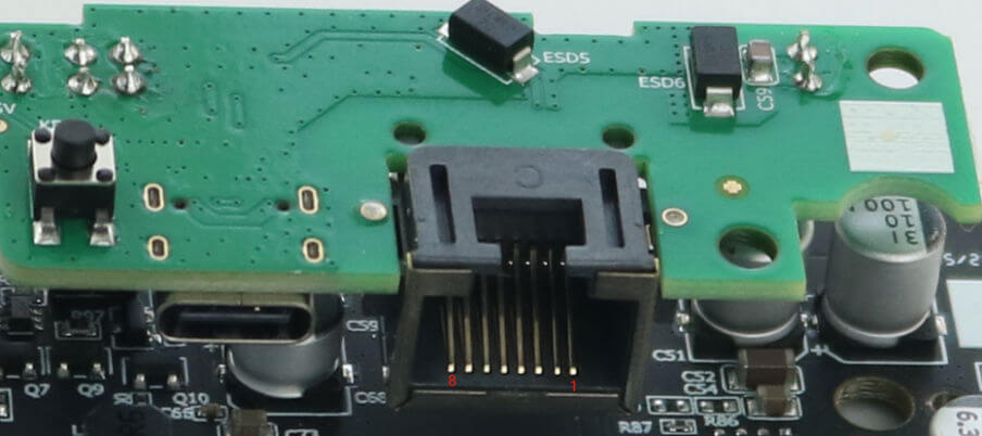
RJ45 is the standard socket of TAP UP, which is compatible with RJ50 terminals. The order is as shown above, and the function definition of the pins is as follows:
| Serial number | Pin Name | Pin Description | IO Level | Remark |
|---|---|---|---|---|
| 1 | VPOS | Power positive | 17V~50V | MJB5 provides power |
| 2 | GND | Power Ground | 0V | |
| 3 | PRQ_N | Main control wake-up control box | 40V | Level determined by MJB5 |
| 4 | NC | No signal connected | ||
| 5 | NC | No signal connected | ||
| 6 | NC | No signal connected | ||
| 7 | CO61_RXD | Master serial port receiving signal | 3.3V | Main control and CO61 data communication interface |
| 8 | CO61_TXD | The master serial port sends a signal | 3.3V |
② RJ45 specification, this socket is compatible with RJ45 and RJ50 heads:
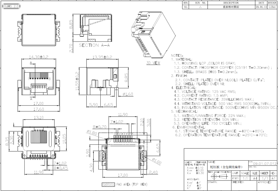
① The pin sequence of TYPE-C J5 on PCBA is shown in the figure below:
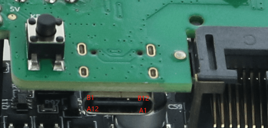
The pin function definitions are as follows:
| Serial number | Pin Name | Pin Description | IO Level | Remark |
|---|---|---|---|---|
| A1 | GND | Power Ground | 0V | Gateway external 5V power supply |
| A4 | VBUS | Power positive | 5.0V | |
| A5 | CC1 | Channel 1 detection | 5.1K resistor from the slave to ground | |
| A6 | DP1 | USB2.0 differential signal, positive of channel 1 | This gateway does not have this function | |
| A7 | DN1 | USB2.0 differential signal, negative of channel 1 | ||
| A8 | SBU1 | Auxiliary functions of channel 1 | ||
| A9 | VBUS | Power positive | 5.0V | Gateway external 5V power supply |
| A12 | GND | Power Ground | 0V | |
| B1 | GND | Power Ground | 0V | |
| B4 | VBUS | Power positive | 5.0V | |
| B5 | CC2 | Channel 2 detection | 5.1K resistor from the slave to ground | |
| B6 | DP2 | USB2.0 differential signal, positive of channel 2 | This gateway does not have this function | |
| B7 | DN2 | USB2.0 differential signal, negative of channel 2 | ||
| B8 | SBU2 | Auxiliary functions of channel 2 | ||
| B9 | VBUS | Power positive | 5.0V | Gateway external 5V power supply |
| B12 | GND | Power Ground | 0V |
② This port is compatible with the standard TYPE-C interface, and the input voltage is 5V/2A;
③ The device datasheet is as follows:
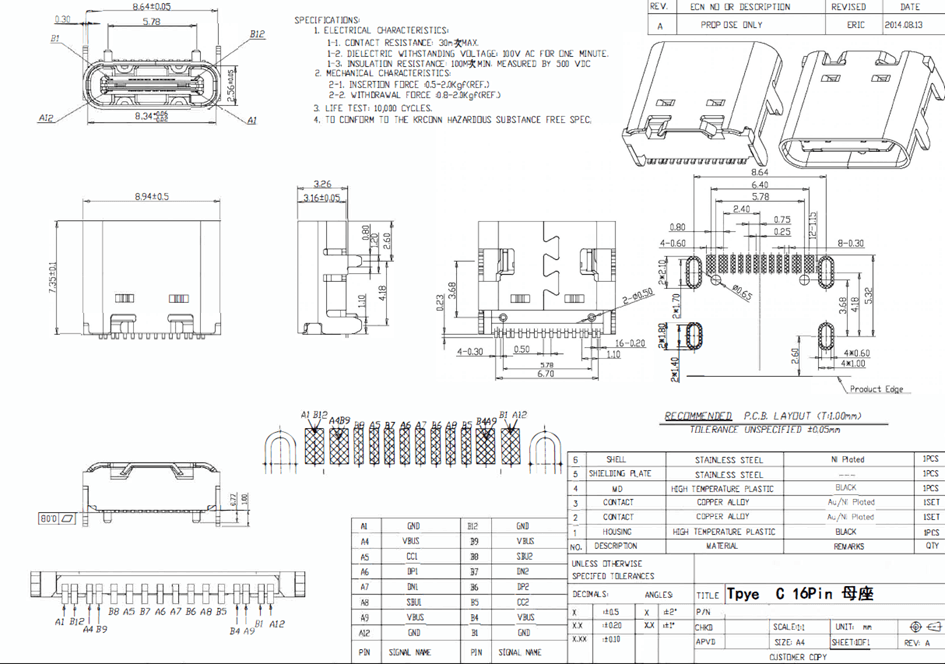
There is only one factory reset button on the small board, and the small board is connected to the main board via a pin header:
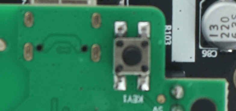
Pressing this button for more than 10 seconds will restore the gateway to factory settings.
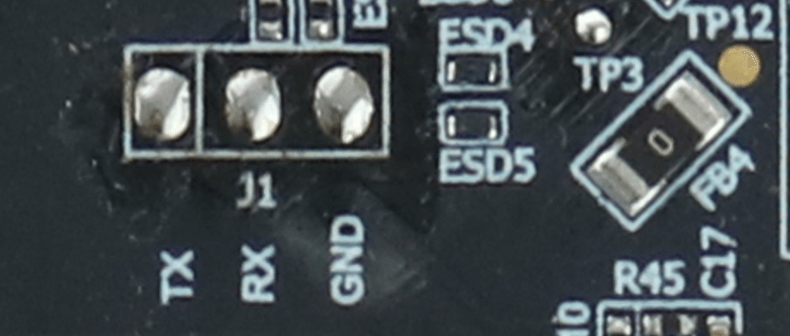
① Three test points J1 with a spacing of 2.54mm are reserved on the mainboard as the lead-out points of the debug serial port, as shown below:
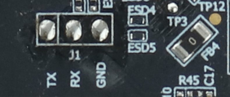
② The definitions of the tests are shown in the silkscreen at the corresponding points, from left to right: TX, RX and GND.
① The WIFI function of the gateway is implemented by the main control module shown in the figure below. The pin definition of the main control module U1 is as follows:
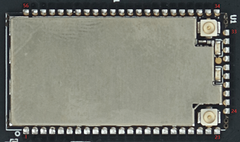
The pin definition is the same as that of the core board.
② The WIFI module supports IEEE802.11b/g/n, 2T2R, 300Mbps data rate. The built-in FPC antenna is led out from the two ipex on the module.
① The BLE function of the gateway is implemented by the BLE module shown in the figure below. The U3 pin of the BLE module is defined as follows:
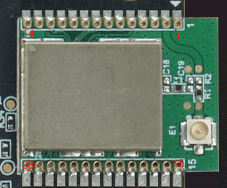
The pin function definitions are as follows:
| Serial number | Pin Name | Pin Description | IO Level | Remark |
|---|---|---|---|---|
| 1 | GND | Systematically | 0V | |
| 2 | ANT | Antenna signal terminal | External RF signal port | |
| 3 | GND | Systematically | 0V | |
| 4 | NC | |||
| 5 | PA0 | GPIO Pins | 3.3V | Can be used for GPIO port applications |
| 6 | PC5 | GPIO Pins | 3.3V | Can be used for GPIO port applications |
| 7 | PC4 | GPIO Pins | 3.3V | Can be used for GPIO port applications |
| 8 | PA3 | GPIO Pins | 3.3V | Can be used for GPIO port applications |
| 9 | PA4 | GPIO Pins | 3.3V | Can be used for GPIO port applications |
| 10 | PC1 | GPIO Pins | 3.3V | Can be used for GPIO port applications |
| 11 | PC0 | GPIO Pins | 3.3V | Can be used for GPIO port applications |
| 12 | PD4 | GPIO Pins | 3.3V | Can be used for GPIO port applications |
| 13 | PD3 | GPIO Pins | 3.3V | Can be used for GPIO port applications |
| 14 | PD2 | GPIO Pins | 3.3V | Can be used for GPIO port applications |
| 15 | NC | |||
| 16 | NC | |||
| 17 | PB0 | GPIO Pins | 3.3V | Can be used for GPIO port applications |
| 18 | PB1 | GPIO Pins | 3.3V | Can be used for GPIO port applications |
| 19 | NC | |||
| 20 | GND | Systematically | 0V | |
| 21 | VCC3V3 | System Power | 3.3V | Module power supply positive electrode |
| 22 | RX0 | Serial port receiving signal | 3.3V | Serial signal input |
| 23 | TX0 | Serial port sends signal | 3.3V | Serial signal output |
| 24 | SWDIO | JTAG Data Port | 3.3V | JTAG debug port |
| 25 | SWCLK | JTAG clock port | 3.3V | |
| 26 | PC3 | GPIO Pins | 3.3V | Can be used for GPIO port applications |
| 27 | PC2 | GPIO Pins | 3.3V | Can be used for GPIO port applications |
| 28 | nRESET | Module reset pin | 3.3V | Module reset function pin |
② The BLE module supports Bluetooth 5.0, and the built-in FPC antenna is led out from the ipex socket on the module.
There are three status indicators on the motherboard, namely LED1, LED2 and LED3. The three status indicators are observed through the light guide on the housing. The positions of the three status indicators on the PCBA are shown in the figure below:
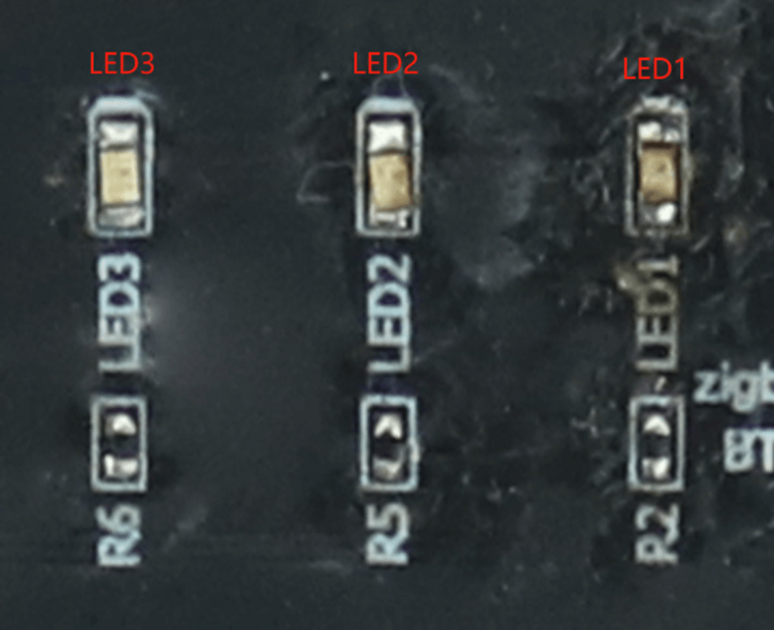
| Serial number | name | color | state | Remark |
|---|---|---|---|---|
| 1 | LED1 | green | Display status can be user defined | Power indicator |
| 2 | LED2 | green | Display status can be user defined | Network status indication |
| 3 | LED3 | green | Display status can be user defined | Control box status indication |
The indicator light colors and status descriptions in this gateway can be defined by the customer software.
4. Software Instructions
The motherboard has a software button by default, which can be modified according to customer needs.
By default, when the button is pressed, the system will call /etc/rc.button/BTN_0 script:
1. Short press and release to turn on the hotspot
2. Press and hold for 5 seconds and then release to restore the factory settings.
					#!/bin/sh
./lib/functions.sh
./lib/functions/leds.sh
if [ "${ACTION}" == "pressed" ];
then
    touch /tmp/BTN_0_pressed
    touch /tmp/btn1
else
    rm -f /tmp/BTN_0_pressed
fi

if [ -f /tmp/dusun_upgrade ] ; then
    exit 0
fi

[ ! "${ACTION}" == "released" ] && {
    exit 0
}

[ "$SEEN" -ge 5 ] && {
    logger "factory reset.."
    led_off zigbee
    led_off pwrled
    led_off errled
    led_timer zigbee 200 200
    led_timer pwrled 200 200
    led_timer errled 200 200
    logger "FACTORY RESET"
    #jffs2reset -y && reboot &
    firstboot -y && reboot &
    exit 0
}

[ "$SEEN" -ge 0 ] && {
    logger "Open Default Ap"
    uci set /etc/config/wireless.radio0.disabled=0; uci commit wireless;
    uci set /etc/config/wireless.ap0.hidden=0; uci commit wireless;
    #/etc/init.d/network restart;
    /etc/init.d/uhttpd restart
    Wi-Fi &
    exit 0
}
It is recommended to use MobaXterm to access, the recommended download address is:
https://mobaxterm.mobatek.net/download-home-edition.html
The effect after the tool opens the serial port is as follows:
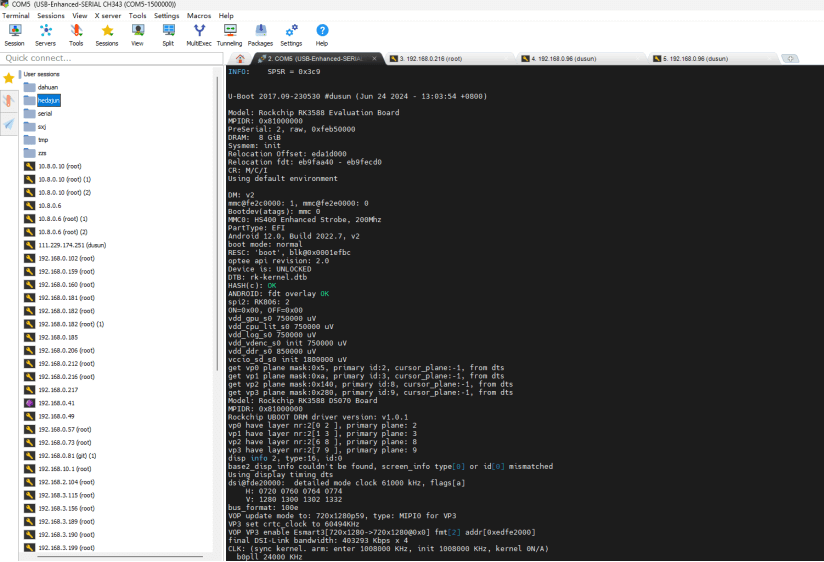
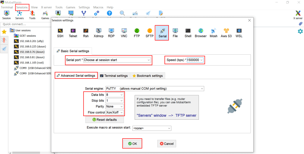
Debug serial port baud rate 57600
1) 8 data bits
2) 1 stop bit
3) No verification
4) No flow control
Please note that the serial port baud rate drop-down box does not have 57600, you need to enter directly.
See the figure below for details.
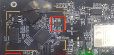
● Remove the spi flash from the board
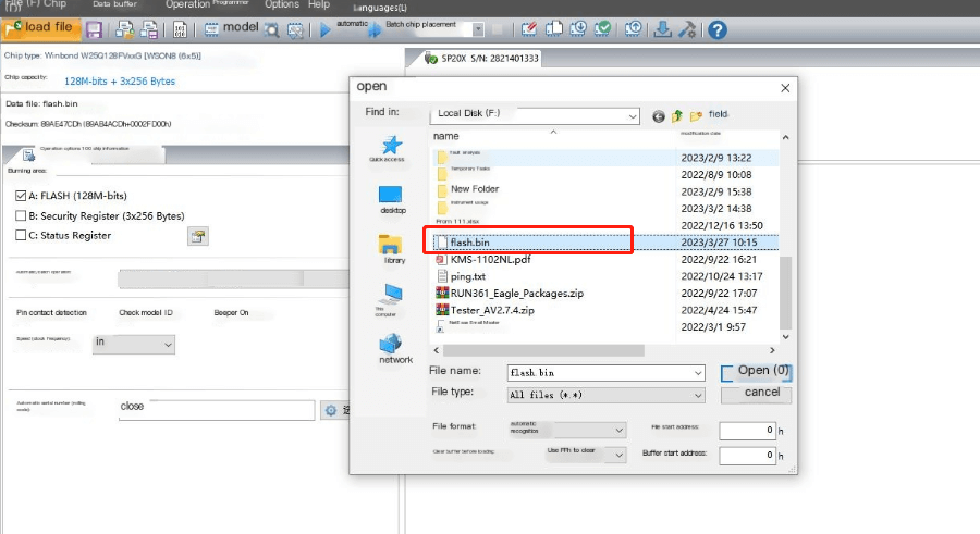
● Put the flash on the SPI Flash burner, select the correct flash model, and then import the burning file
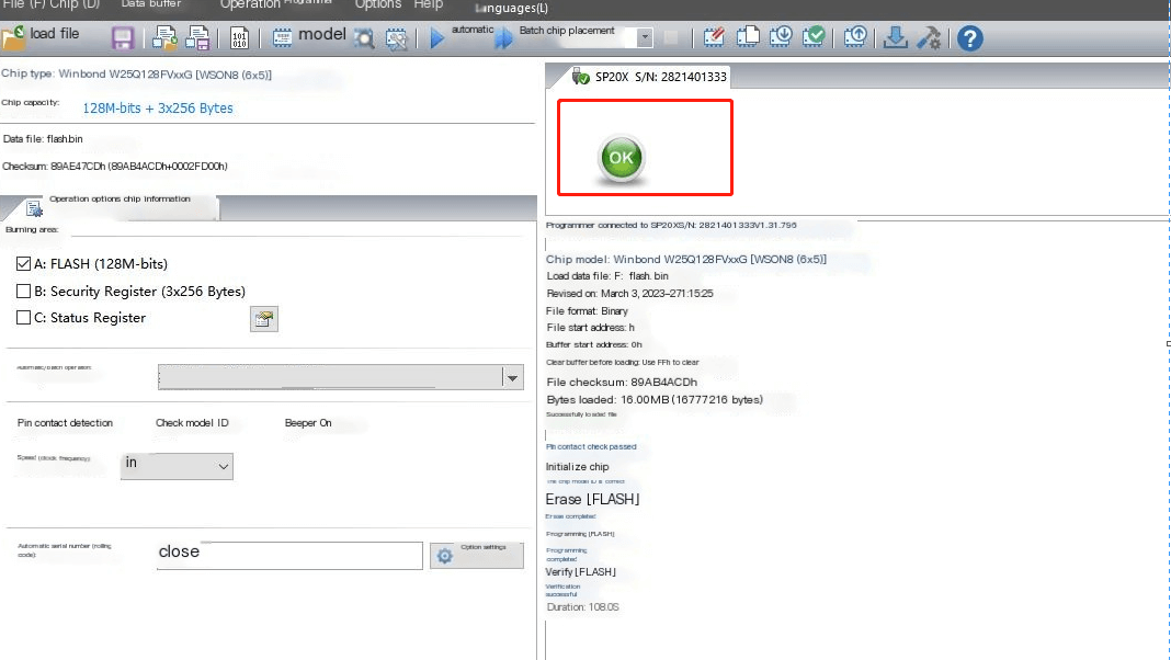
● Press Auto Burn


● Wait for the burning to be successful, then reattach the flash to the board
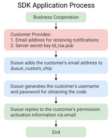
The SDK versions of Dusun’s different chip platforms need to be applied to the corresponding business end respectively. For example, your company has received the SDK for MT7628, and now there is a new project that requires the SDK for MT7621. We need to contact the corresponding business end of Dusun for business confirmation, and the business end will assist in the application. After approval by Dusun’s reviewers, the technical department can disclose information to your company.
Notice:
The SDK code management released by Dusun follows Google’s REPO method. Users are not recommended to delete the SDK’s REPO and GIT version records.
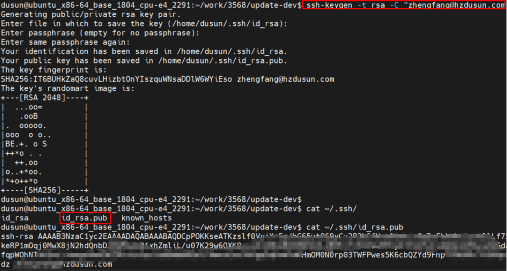
Enter on the server command line
ssh-keygen -t rsa -C " xxxx@xxxx.com "
2. Keep pressing Enter without entering any task characters;
3. After generating the key, email the ~/.ssh/id_rsa.pub file to Dusun
Enter on the server command line:
					git config --global user.email " You@example.com "
git config --global user.name "Your Name"
git clone ssh:// git@roombanker.x3322.net :2223/dusun_repo.git
					sudo cp -f ~/work/dusun_repo/repo /usr/bin/repo
sudo chmod +x /usr/bin/repo
					mkdir -p ~/work/project/dev
cd ~/work/project/dev
repo init -u ssh:// git@roombanker.x3322.net :2223/mtk7628_op/manifests_first.git -m linux.xml -b 090 --no-repo-verify
repo sync -c -j8
repo start master --all
					mkdir -p ~/workdir
tar zxvf DSGW-090-ondo_sdk_AVV4.8.332.49212713.tar.gz -C ~/workdir/
cd ~/workdir/
./build.sh
					openwrt-ramips-mt76x8-DSGW021-squashfs-sysupgrade.binUpgrade the firmware for the system
[au@git openwrt]$ ls ./bin/targets/ramips/mt76x8/ -alh
total 138M
drwxr-xr-x 3 au au 4.0K Jun 1 2022 .
drwxr-xr-x 5 au au 48 Sep 30 2021 ..
-rw-r--r-- 1 au au 122 Mar 24 17:40 config.buildinfo
-rw-r--r-- 1 au au 263 Mar 24 17:40 feeds.buildinfo
-rw-r--r-- 1 au au 4.9K Mar 16 21:31 openwrt-ramips-mt76x8-device-dsgw090.manifest
-rw-r--r-- 1 au au 14M Mar 16 21:31 openwrt-ramips-mt76x8-DSGW021-squashfs-sysupgrade.bin
drwxr-xr-x 2 au au 12K Mar 24 17:12 packages
-rw-r--r-- 1 au au 2.8K Mar 24 17:41 sha256sums
-rw-r--r-- 1 au au 18 Mar 24 17:40 version.buildinfo
The wifi configuration under Openwrt is achieved by modifying the /etc/config/wireless configuration file.
					root@DSGW090:~# cat /etc/config/wireless
config wifi-device 'radio0'
    option type 'mac80211'
    option channel 'auto'
    option hwmode '11g'
    option noscan '1'
    option path 'platform/10300000.wmac'
    option htmode 'HT40'
config wifi-iface 'ap0'
    option device 'radio0'
    option network 'lan'
    option mode 'ap'
    option ssid 'Dusun-E3AD24-2.4G'
    option encryption 'psk2'
    option key '7BE3AD24'
					root@DSGW090:~# cat /etc/config/wireless
config wifi-device 'radio0'
    option type 'mac80211'
    option channel 'auto'
    option hwmode '11g'
    option noscan '1'
    option path 'platform/10300000.wmac'
    option htmode 'HT40'
config wifi-iface 'sta0'
    option device 'radio0'
    option network 'wwan0'
    option mode 'sta'
    option ssid 'AAAAAA'
    option encryption 'psk2'
    option key 'dl123456'

admin@DSGW090:/root# cat /etc/config/network
... //Other content
    config interface 'wwan0'
    option proto 'dhcp'
    option metric '1'
    option ifname 'wlan0'
    option mtu '1492'
... //Other content
This gateway has only one WAN port, configured in /etc/config/network
					root@DSGW090:~# cat /etc/config/network
... //Other configuration
config device 'lan_wlan0_dev'
    option name 'wlan0'
    option macaddr '30:ae:7b:e3:ad:25'
config device 'lan_wlan1_dev'
    option name 'wlan1'
    option macaddr '30:ae:7b:e3:ad:25'
config interface 'wan'
    option ifname 'eth0'
    option proto 'dhcp'
    option mtu '1492'
config device 'wan_eth0_dev'
    option name 'eth0'
    option macaddr 'ff:ff:ff:ff:00:00'
config interface 'wan6'
    option ifname 'eth0'
    option proto 'dhcpv6'
// Other configuration
The default is DHCP mode. If you need to configure it to a static IP, you can configure it on the page. The configuration after configuration should be similar to the following
					root@DSGW090:~# cat /etc/config/network
... //Other configuration
config device 'lan_wlan0_dev'
    option name 'wlan0'
    option macaddr '30:ae:7b:e3:ad:25'
config device 'lan_wlan1_dev'
    option name 'wlan1'
    option macaddr '30:ae:7b:e3:ad:25'
config interface 'wan'
    option ifname 'eth0'
    option proto 'static'
    optionipaddr '192.168.100.33'
    optiongateway '192.168.100.1'
    optionnetmask '255.255.255.0'
    option dns '192.168.100.1 '
    option mtu '1492'

config device 'wan_eth0_dev'
    option name 'eth0'
    option macaddr 'ff:ff:ff:ff:00:00'
config interface 'wan6'
    option ifname 'eth0'
    option proto 'dhcpv6'
// Other configuration
The default LTE module of this gateway is EG91
● Apn configuration file /etc/config/ppp
					root@DSGW090:/root# cat /etc/config/ppp
config ppp 'ppp'
  option apn 'em'
  option password ''
  option username ''
● Dial-up script configuration
					root@DSGW-010:~# ls /etc/ppp/peers/* -alh
-rwxr-xr-x 1 root root 359 Feb 27 2020 /etc/ppp/peers/dial
-rwxr-xr-x 1 root root 163 Feb 27 2020 /etc/ppp/peers/mo_3gmodule.dial
● By default, the gateway will start dialing when the network cable and wifi are not connected. You can manually start the script during debugging.
					/etc/init.d/netmge stop Stop the dial-up script
echo 0 > /sys/class/gpio/gpio40/value    Enable lte module
pppd call dial                           Start dialing

Modify the dial-up script front-end log
root@DSGW-010:~# cat /etc/ppp/options
debug                // remove #, open the debug mode
nodetach            // add this
#logfile /dev/null  // comment this line
noipdefault

root@DSGW-090:~# pppd call dial
timeout set to 3 seconds
send (ate0^M)
expect (OK)
^M
OK
-- got it
send (at^M)
expect (OK)
^M
^M
OK
-- got it
send (AT+CSQ^M)
expect (OK)
^M
^M
+CSQ: 99,99^M
^M
OK
-- got it
send (AT+COPS?^M)
expect (OK)
^M
^M
+COPS: 0^M
^M
OK
-- got it
send (AT+CREG?^M)
expect (OK)
^M
^M
+CREG: 0,0^M
^M
OK
-- got it
send (AT+CEREG?^M)
expect (OK)
^M
^M
+CEREG: 0,0^M
^M
OK
-- got it
send (AT+CPIN?^M)
expect (READY)
The motherboard has a software button by default, which can be modified according to customer needs.
By default, pressing the button will call/etc/rc.button/BTN_0 script:
1. Short press and release to turn on the hotspot
2. Press and hold for 5 seconds and then release to restore the factory settings.
					#!/bin/sh
./lib/functions.sh
./lib/functions/leds.sh
if [ "${ACTION}" == "pressed" ];
then
    touch /tmp/BTN_0_pressed
    touch /tmp/btn1
else
    rm -f /tmp/BTN_0_pressed
fi

if [ -f /tmp/dusun_upgrade ] ; then
    exit 0
fi

[ ! "${ACTION}" == "released" ] && {
    exit 0
}

[ "$SEEN" -ge 5 ] && {
    logger "factory reset.."
    led_off zigbee
    led_off pwrled
    led_off errled
    led_timer zigbee 200 200
    led_timer pwrled 200 200
    led_timer errled 200 200
    logger "FACTORY RESET"
    #jffs2reset -y && reboot &
    firstboot -y && reboot &
    exit 0
}

[ "$SEEN" -ge 0 ] && {
    logger "Open Default Ap"
    uci set /etc/config/wireless.radio0.disabled=0; uci commit wireless;
    uci set /etc/config/wireless.ap0.hidden=0; uci commit wireless;
    #/etc/init.d/network restart;
    /etc/init.d/uhttpd restart
    Wi-Fi &
    exit 0
}
					echo none > /sys/class/leds/pwrled/trigger
echo 1 > /sys/class/leds/pwrled/brightness
					echo none > /sys/class/leds/pwrled/trigger
echo 0 > /sys/class/leds/pwrled/brightness
					echo timer > /sys/class/leds/pwrled/trigger
echo 500 > /sys/class/leds/pwrled/delay_on
echo 500 >/sys/class/leds/pwrled/delay_off
This board has a ble Bluetooth chip EFR32BG21, and the default ncp program is used
● By default, specific operations can be performed on the Bluetooth page of the luci page.
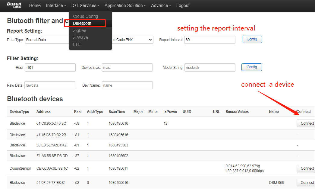
● If you want to debug the module manually, or write your own Bluetooth program, you need to stop the default Bluetooth program
/etc/init.d/beacond stop; killall -9 bul; killall -9 hciattach;
● Get tty device
					find /sys/bus/usb/devices/1-1.4:1.0/ -name "ttyUSB*" -maxdepth 1
/dev/ttyUSB0 //Here it is assumed to be ttyUSB0, the actual value shall prevail
● Get the version
/usr/bin/bflash -d /dev/ttyUSB0 -b115200 -r1
5. Relevant standards and certifications
Chinese Standard: GB/T 26572-2011
EU Standard: Directive 2011/65/EU
Note: The components used in the current product comply with ROHS standards
EU Standard: EU Regulation (EC) No 1907/2006 (REACH)
Note: The components used in the current product comply with REACH standards.
| 1 | Random vibration test | 1. Place 3 noodles on the platform for 30 minutes. 2. Place Noodle 1 on the platform for 10 minutes. 3. Place side 2 or side 4 on the platform for 10 minutes. 4. Place surface 5 or 6 on the platform for 10 minutes. 5. Frequency: 1…4…100…200 6. PSD: 0.0001…0.01…0.01…0.0001 |
There is no obvious damage to the box after the random vibration test |
| 2 | Fixed displacement test | Displacement: 25 mm Displacement times: 14200 ci |
There is no obvious damage to the box after the displacement test |
| 3 | Sinusoidal vibration test (packaging) |  |
1. The appearance, function and performance of the equipment under test meet the specifications of the relevant standards without obvious changes, and the functions of the equipment meet the requirements of Table 2. 2. Minor surface damage (such as scratches, nicks, etc.) of the sample meets the requirements. 3. Some parts of the sample (such as connectors) are allowed to have slight deformation, but this deformation cannot affect the mechanical and electrical properties of the device. |
| 4 | Sinusoidal vibration test (bare metal) |  |
1. The appearance, function and performance of the equipment under test meet the specifications of the relevant standards without obvious changes, and the functions of the equipment meet the requirements of Table 2. 2. Minor surface damage (such as scratches, nicks, etc.) of the sample meets the requirements. 3. Some parts of the sample (such as connectors) are allowed to have slight deformation, but this deformation cannot affect the mechanical and electrical properties of the device. |
| 1 | Package drop test | 1. Wt< 10 Kg, drop 97 cm, 2. Wt:10 ~ 19 Kg, drop 81 cm, 3. 19 ~ 28 Kg, drop 66 cm, 4. Test standard: one corner, three sides, six faces, ten drops in total.  |
There is no obvious damage to the box after the drop test |
| 2 | 1. Sample with normal function, no power supply 2. Drop mode: 6 sides, the drop sides are bottom, front, left, right, back and front in order; 3. Drop height a) Excluding display screen and optical engine products Free fall from a height of 100 cm onto a wooden floor no less than 3 cm thick b) Products containing display screens and optical engines Free fall from a height of 80cm onto a wooden floor no less than 3cm thick |
1. The appearance, function and performance of the equipment under test meet the specifications of the relevant standards without obvious changes, and the functions of the equipment meet the requirements of Table 2. 2. Minor surface damage (such as scratches, nicks, etc.) of the sample meets the requirements. 3. Some parts of the sample (such as connectors) are allowed to have slight deformation, but this deformation cannot affect the mechanical and electrical properties of the device. |
|
| 3 | Drop (Packaging) | 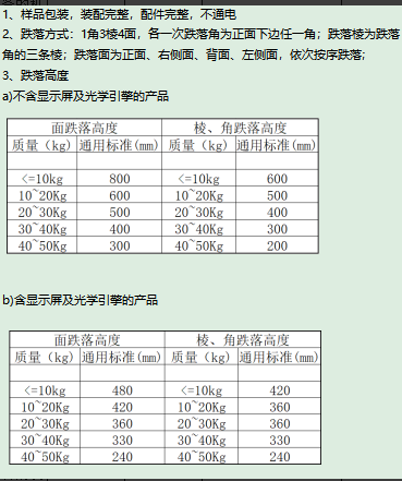 |
1. The appearance, function and performance of the equipment under test meet the specifications of the relevant standards without obvious changes, and the functions of the equipment meet the requirements of Table 2. 2. Minor surface damage (such as scratches, nicks, etc.) of the sample meets the requirements. 3. Some parts of the sample (such as connectors) are allowed to have slight deformation, but this deformation cannot affect the mechanical and electrical properties of the device. |
EU standards: EN55032:2015 + A11:2020 / EN55035:2017 + A11:2020 / ETSI EN 301489-1 V2.2.3 (2019-11) / ETSI EN 301489-X
Chinese Standard: GB/T 26572-2011
Note: The current product is designed strictly in accordance with EMC standards
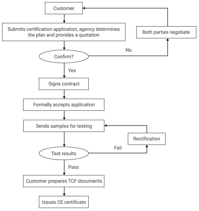
The customer only needs to provide the application company information, and Dusun will be responsible for all the certification processes
The certification process is shown in the following example (CE certification):
① Dusun provides certification related materials, the list of materials is as follows (contact the project leader, who will coordinate and organize the materials):
1. BOM list (all in English)
2. Body Label
3. Block diagram
4. Parts placement
5. PCB layout
6. Schematic diagram SCH
7. User manual
8. Antenna Specifications
9. List of key safety components (with safety component certificates, such as relays, fuses, terminal blocks, etc.)
10. PCB-UL certificate
② Dusun provides certification technical support (fixed frequency, safety regulations, EMC)
Contact the project leader, who will coordinate with relevant technical personnel to provide technical support
6. Order
⚠️:Order sub-model and corresponding product description

