1.Product Introduction
based on Rockchip RK3308J Designed for Oil depot data collection and management A model created High reliability and high stability Embedded Mother board product.The product CPU is ARM quad-core 64-bit Cortex-A35 core, main frequency 1.3GHz, Support high-precision data collection, fast processing and transmission, Fully satisfied Scenario requirements for rapid collection, processing and response of oil depot data, Its hardware design complies with -40~85°C industrial standards, and its product structure is compatible with explosion-proof + flameproof design. Applies to Outdoor oil and gas are flammable and explosive Harsh scenarios.product Support flexible selection of operating system, standard configuration Openwrt The system facilitates customer micro-development to achieve customer cloud docking and customer application migration.
| Name | Describe |
|---|---|
| Product Model | DSGW-560 |
| CPU | RK3308J |
| RAM | 512MB |
| EMMC | 64GB |
| System | Openwrt 21.02 |
| Network port | 1 10/100Mbps Ethernet interface |
| USB3.0 interface | 1 USB2.0 OTG port |
| Wi-Fi | WiFi6, 802.11a/b/g/n/ac/ax 1200Mbps WLAN + BT v5.4, 2 ipex antenna sockets |
| RTC | Support, with 1.25*2pin socket, for non-rechargeable batteries |
| Debug interface | Support, 1 UART interface on board |
| Button | 1 user button |
| 1 hard reset button | |
| 1 RECOVERY button | |
| LED | Flash control interface |
| WiFi working status indicator light control interface | |
| Power supply | DC power supply voltage range 12V/1A or 24V/0.5A |
| Operating temperature | -40 to 85 degrees |
| Storage temperature | -40 to 85 degrees |
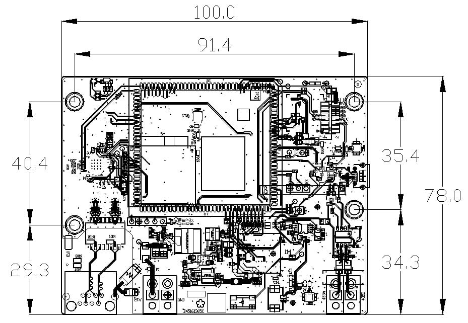
| PCBA Dimensions | 100*78mm |
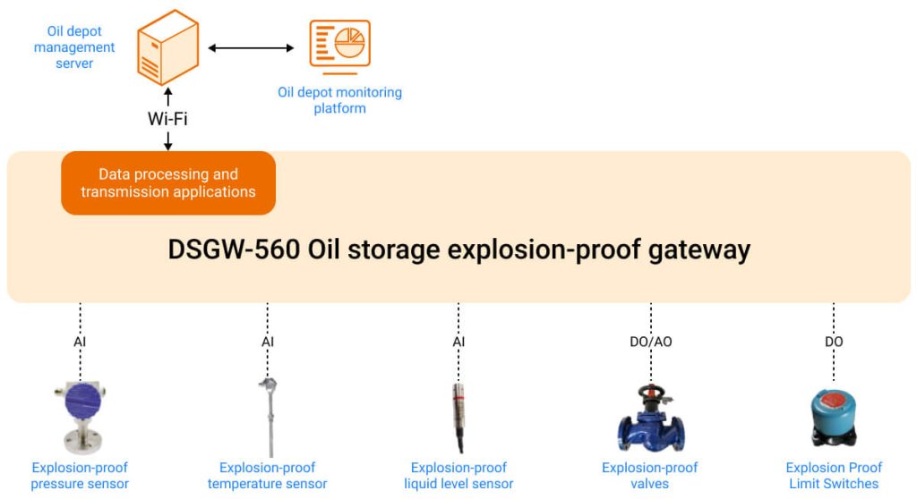
- Functional description of oil storage explosion-proof IoT scenario:
- Sensor data acquisition and control
DSGW-560 oil storage gateway supports multiple high-precision AI, AO, DI, and DO interfaces, and can connect various intelligent sensors and controllers in oil depot management scenarios. - Local data processing and transmission
It supports built-in RTC and local storage of sensor historical data. It also has built-in data transmission application and dual redundant data transmission design. It performs independent transmission after dual-channel data encryption to ensure the stability and reliability of data transmission.
- Dusun Oil Storage Explosion-proof Gateway Advantages:
- High-precision data acquisition
The data acquisition circuit is optimized and designed, using low-temperature drift and high-precision components. The AO and AI acquisition accuracy reaches 1% over the full temperature range. - Low latency
Optimize data collection and processing processes, customize data transmission applications, and ensure that the delay of the entire process from collection to transmission is less than 50ms. - Explosion-proof + flameproof design
The circuit adopts explosion-proof + flameproof design, the power supply is intrinsically safe design, and the product has high stability.
Dusun customizes high-reliability operating systems and industry SDKs based on standard systems and industrial control industry-related applications. With years of experience in the development and design of robot embedded motherboards, it completes the transplantation and testing of a variety of hardware peripheral drivers that meet industry applications. The following is the software framework of the default Openwrt system of DSGW-560.
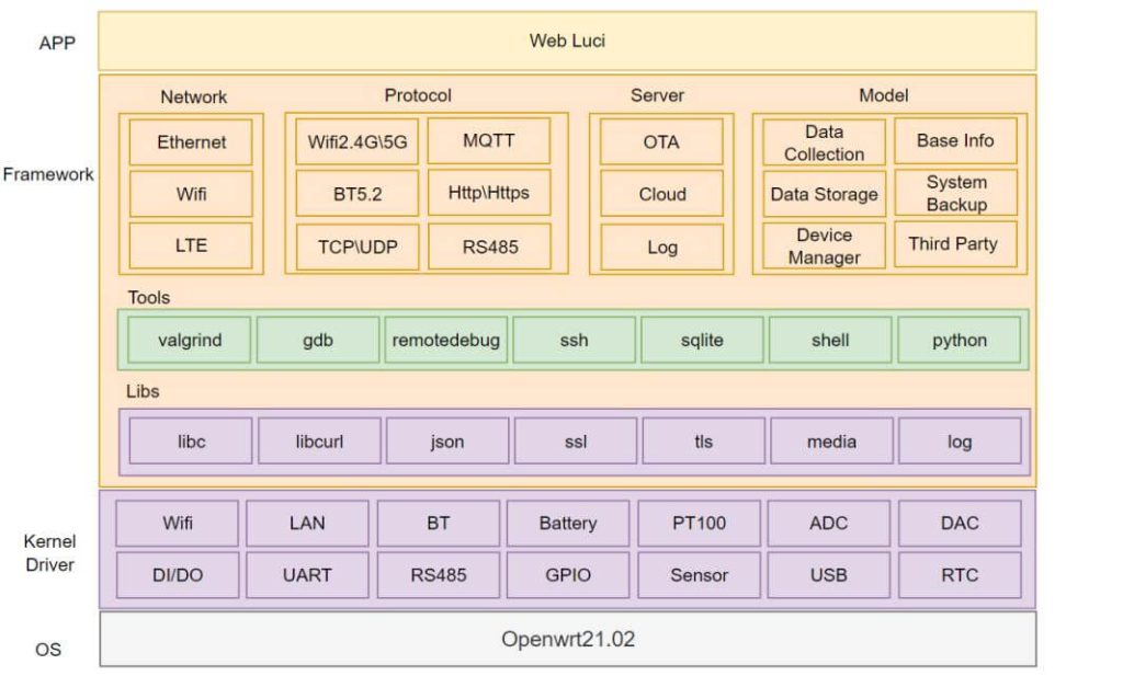
In addition, Dusun can provide independent system support for various versions of Linux, such as Debian, Ubuntu, etc.
Dusun provides industrial control industry SDK source code that matches the industrial control motherboard, supporting customers to conduct micro-development to achieve rapid productization. Dusun Industrial Control Industry SDK has the following features:
- Streamlined operating system: On the premise of meeting industry applications, the number of components is streamlined, the system resource utilization rate is high, thereby reducing hardware costs, and to a certain extent, the functional structure is optimized, the system architecture is reasonably laid out, and the system is more efficient and easy to maintain;
- BSP with industry attributes: According to the types of peripheral devices used in the industry, driver transplantation and debugging are carried out and industry algorithms are adapted to meet the customer’s needs for selecting an overall hardware + algorithm solution. In addition, Dusun BSP driver will continue to iterate the access to peripheral devices of different brands and models.
- Pre-installed tools and middleware: Commonly used testing tools, as well as customized tools required by customers, etc., make it easy for users to quickly transplant applications and tree models of other hardware platforms and achieve low-cost hardware platform switching.
- Industry application software: Built-in application software optimizes the process of data collection and processing, and the software realizes dual-channel data transmission.
| Peripherals | model | illustrate |
|---|---|---|
| Intrinsically safe power supplies | -- | -- |
Core algorithms available upon request
| Matching peripheral hardware | model | illustrate |
|---|---|---|
| Pressure Sensors | JYB-KB-P (Collihigh) | ATEX explosion-proof pressure sensor |
| Thermal resistor | ZNC004(Guide car) | Explosion-proof thermal resistor PT100, L=70mm |
| Liquid level sensor | L8000T (Honeywell) | Explosion-proof liquid level sensor |
| Oil depot valve | VBA216-100F(Honeywell) | Electric Flange ball valve |
| Emergency limit switch | - | Explosion Proof Limit Switches |
NA
2. Installation Instructions
1. Product shipped without accessories
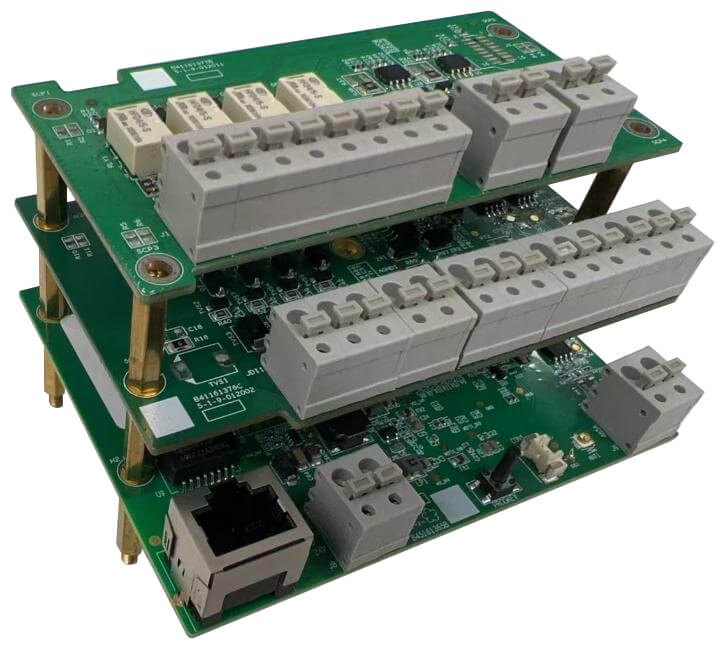
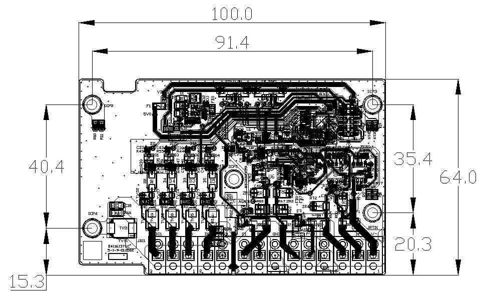
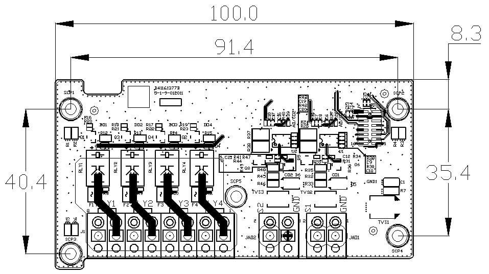
1. The whole product has 3 PCBAs. It is recommended to use copper nuts to space and fix them. As shown in the figure below.
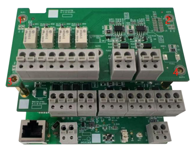
2. The product is fixed by 4 screws (the fixing hole positions are shown in the figure below). The screw hole diameter is 3.3±0.15mm. It is recommended to use M3x6mm cross pan head screws.
1. Key dimensions of the base plate:
2. Key dimensions of the middle plate:
3. Key dimensions of the upper board:
3. Hardware Instructions
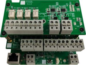
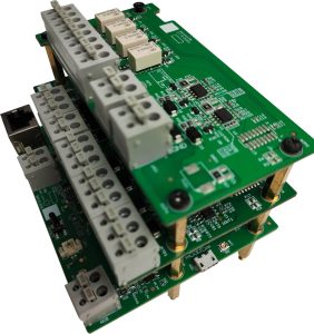
| Serial number | describe | Notes (If it is a seat, the order is from left to right as shown in the picture) |
| 1 | 12V/1A or 24V/0.5A power input socket | Vin, GND |
| 2 | RJ45 Ethernet port | 10/100Mbps |
| 3 | User Buttons | Customizable features |
| 4 | RTC 1.25*2pin battery holder | Connect to non-rechargeable battery, pin 1 is positive and pin 2 is negative |
| 5 | FGS061N WiFi module ipex antenna seat | Ipex 1/2 generation |
| 6 | RS-485 connector | 485A, 485B, no isolation |
| 7 | USB 2.0 micro-B | USB 2.0 OTG, for burning |
| 8 | FCS960K-E WiFi module ipex antenna seat | Ipex 1/2 generation |
| 9 | RGB three-color light | Customizable features |
| 10 | Reserved wireless module ipex antenna base | Ipex 1/2 generation |
| 11 | Digital/pulse input connector JDI1 | Pulse input 1, pulse input 2, pulse input 3 |
| 12 | Digital/pulse input connector JDI2 | Pulse input 4, GND |
| 13 | 4-20mA analog input connector JAI1 | 4-20mA input, 24V output, GND |
| 14 | 4-20mA analog input connector JAI2 | 4-20mA input, 24V output, GND |
| 15 | PT100 three-wire thermal resistance detection seat | Common line terminal, common line terminal, individual line terminal |
| 16 | STM32 4pin debug socket | 3V3, GND, TX, RX |
| 17 | STM32 4pin burning socket | 3V3, SWDIO, GND, SWCLK, |
| 18 | Digital/relay output socket (voltage-free) | Relay 1 outputs NO, Relay 1 outputs COM, Relay 2 outputs NO, Relay 2 outputs COM, Relay 3 outputs NO, relay 3 outputs COM, Relay 4 outputs NO, relay 4 outputs COM, |
| 19 | 4-20mA analog output socket JAO2 | 4-20mA output, GND |
| 20 | 4-20mA analog output socket JAO1 | 4-20mA output, GND |
There is an RGB tricolor light on the PCBA (9 in the 3.2.1 Interface Identification Figure). The specific lighting mode can be customized through the corresponding GPIO. An example is given below:
| Serial number | Light status | Product working status |
|---|---|---|
| 1 | Green light is always on | Normal operation |
| 2 | Flashing red light | 1 WiFi abnormality |
| 3 | Red light is on | 2 WiFi anomalies |
| 4 | Blue light flashing | IO board abnormality |
| 5 | Red and blue lights flash alternately | 1 WiFi abnormality + IO board abnormality |
4. Relevant standards and certifications
Chinese Standard: GB/T 26572-2011
EU Standard: Directive 2011/65/EU
Remark:The components used in current products comply with ROHS standards
EU Standard: EU Regulation (EC) No 1907/2006 (REACH)
Remark:The components used in the current products comply with REACH standards
EU standards: EN55032:2015 + A11:2020 / EN55035:2017 + A11:2020 / ETSI EN 301489-1 V2.2.3 (2019-11) / ETSI EN 301489-X
Chinese Standard: GB/T 26572-2011
Note: The current product is designed strictly in accordance with EMC standards
The customer only needs to provide the application company information, and Dusun will be responsible for all the certification processes
The certification process is shown in the following example (CE certification):
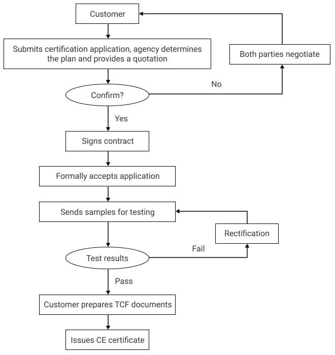
① Dusun provides certification related materials, the list of materials is as follows (contact the project leader, who will coordinate and organize the materials):
- BOM list (all in English)
- Body Label
- Block diagram
- Parts placement
- PCB layout
- Schematic diagram SCH
- User manual
- Antenna Specifications
- List of key safety components (with safety component certificates, such as relays, fuses, terminal blocks, etc.)
- PCB-UL certificate
② Dusun provides certification technical support (fixed frequency, safety regulations, EMC)
Contact the project leader, who will coordinate with relevant technical personnel to provide technical support
5. Ordering - Product Manager
⚠️:Order sub-model and corresponding product description

