1. Introduction
A simple, easy to use programmable thermostat has the features you want, such as a large touch-screen display and Smart Response Technology. You set it up to adjust the temperature when you are away or asleep-times when you don’t necessarily need to heat or cool your home to optimum comfort-and your HVAC equipment and heat pump runs less.
It automatically adjusts the heating/cooling of your home, so you’re comfortable at your programmed times. With Auto Change from Heat to Cool, the switch from heating to cooling is automatic.
- Negative black screen will bring you to a secret world
- 4.8 inch large colorful display creates your colorful life.
- Touch buttons to make simple operation
- Amazing silver frame opens your modern life.
- The visible thickness above the wall is only 2cm(0.787inch)
- The snap connection allows you to easily install.
- Wall mounted or suitable for the installation of Europe, China, Japan, USA and Italy etc..
- White, black or brushed stainless steel for your selection.
- Wrap-around cooling holes help heat to escape quickly and increase the temperature sensing accuracy.
- 12 terminals are available for many systems.
- Powerful functions are available such as Zigbee、WiFi,etc..
- 0.5 °C / 1°F accuracy keeps the temperature within the level you set.
- °C or °F choice
- 7 day programmable (each day can be set different)
- Temporary programmable
- Holiday mode: make you enjoy a more comfortable temperature in holiday
- All setting languages synchronize your time zone, address, and language
- No limit to add thermostats in App.
- Support Smart Scene.
- Support to make two stage groups.
- Support device sharing.
- Support 3H2C Heat Pump system and 2H2C conventional system et..
2. Dimension

3. Touch screen quick reference
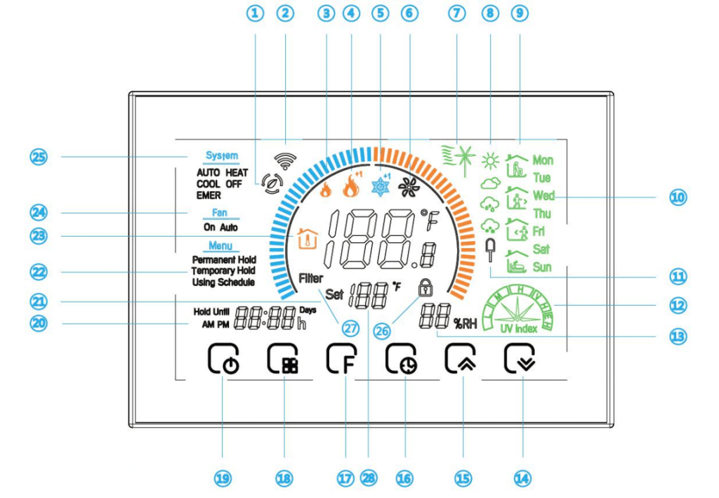
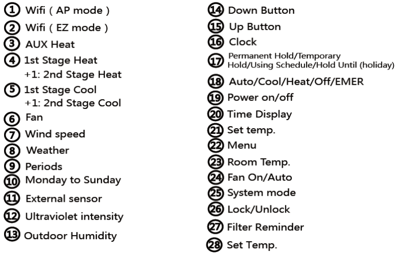
4. Technical data
| Category | Specifications |
|---|---|
| Power | 24VDC/AC ±10% |
| Sensor | NTC3950, 10K |
| Current Load | 1A(Inductive) 3A(Resistance) |
| Product Type | Heat Pump Thermostat |
| Set Temp. Range | 42~122°F (5~45°C) |
| Accuracy | ±1°F |
| Display Temp. Range | 41~210℉(5~99℃) |
| Ambient Temp | 32~113℉(0~45℃) |
| Ambient Humidity | 5 ~95%RH(Non-Condensing) |
| Storage Temp | 23~113°F(-5~45°C) |
| Protocol | Wi-Fi |
| WI-FI Performance | IEEE wireless LAN standard: IEEE802.11n; IEEE802.11g; IEEE 802.11b Data Rate: IEEE 802.11b Standard Mode:1,2,5.5,11Mbps IEEE 802.11g Standard Mode:6,9,12,18,24,36,48,54 Mbps IEEE 802.11n:MCS0~MCS7 @ HT20/ 2.4GHz band MCS0~MCS7 @ HT40/ 2.4GHz band Sensitivity: HT40 MCS7 : -70dBm@10% PER(MCS7) /2.4GHz band HT20 MCS7 : -71dBm@10% PER(MCS7) /2.4GHz band Transmit Power: IEEE 802.11n: 16dBm @HT20/40 MCS7 /2.4GHz band IEEE 802.11g: 16dBm @54MHz IEEE 802.11b: 18dBm @11MHz Wireless Security: WPA/WPA2, WEP, TKIP, and AES Frequency offset: +/- 50KHZ Frequency Range (MHz): 2400.0~2483.5 E.i.r.p (Equivalent Isotropically Radiated Power) (mW)<100mW Bandwidth (MHz):20MHz/40MHz Modulation: BPSK/QPSK, FHSSCCK/DSSS, 64QAM/OFDM |
| Installation | Wall-mounted or on battery seat |
5. Before wiring and installing
Your thermostat can be mounted horizontally on the wall or on a 4 in. x 2 in. (101.6 mm x 50.8 mm) wiring box.
How to select the location?
Install your thermostat about 5ft.(1.5m)above the floor in an area with good air circulation at average temperature.
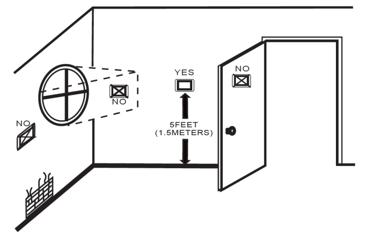
Don’t install your thermostat where it could be affected by:
-Drafts or dead spots behind doors and in corners.
-Hot or cold air from ducts.
-Radiant heat from sun or appliances.
-Concealed pipes and chimneys.
-Unheated (uncooled) areas.
Step 1. Keep the electricity off.
Step 2.Remove the mounting plate. See fig1.

Step 3. Complete the wiring according to the wiring diagram and select the appropriate hole mounting screws. See Fig 2.

Step 4.Check whether the wiring is correct and look for the correct direction of the thermostat display panel. See Fig 3.

Step 5. Press the thermostat back onto the mounting plate to complete the installation.

6. Operation
Press and hold ![]() for 3 seconds when thermostat is off. The device will enter the pairing mode.
for 3 seconds when thermostat is off. The device will enter the pairing mode.
The backlight will be on and the ![]() will be flash one time per spec in the pairing mode. This process will last 90 seconds.
will be flash one time per spec in the pairing mode. This process will last 90 seconds.
Press ![]() to turn the thermostat on/off.
to turn the thermostat on/off.
Press ![]() to select the mode AUTO, COOL, HEAT, OFF, EMER.
to select the mode AUTO, COOL, HEAT, OFF, EMER.
HEAT: Thermostat controls the heating system.
OFF: Both heating and cooling systems are off.
COOL: Thermostat controls the cooling system.
AUTO: Thermostat automatically changes between heating and cooling operation, depending on indoor temperature.
EMER: Emergency heat cycles to maintain temperature. Compressor is locked out (used only for 2H/1C or 3H/2C heat pump systems) and auxiliary heat turns on as second stage if needed.
Press ![]() to set the Permanent Hold, Temporary Hold, using Schedule and hold until (holiday). The functions will appear on the screen.
to set the Permanent Hold, Temporary Hold, using Schedule and hold until (holiday). The functions will appear on the screen.
Permanent Hold –Manual: In this mode, press ![]() to set temperature by manual.
to set temperature by manual.
Temporary Hold: During using schedule or in this mode, press![]() to set the temporary temp. It will be valid till the start time of the next scheduled period.
to set the temporary temp. It will be valid till the start time of the next scheduled period.
Using Schedule: 7days a week, four periods programmable daily.
Holiday Mode: Changes temperature setting for a designated number of days.
Press ![]() till the min of time will flashes;
till the min of time will flashes;
Touch the icon ![]() to set your minute;
to set your minute;
Then press ![]() , the hour of time will flash; touch the icon
, the hour of time will flash; touch the icon ![]() to set your hour;
to set your hour;
Then press ![]() , the week of time will flash; touch the icon
, the week of time will flash; touch the icon ![]() to set your week;
to set your week;
Press ![]() four times in a row. (You can see
four times in a row. (You can see ![]() and
and ![]() )
)
Use the ![]() arrows to adjust the time for the 1st period (Get Up)
arrows to adjust the time for the 1st period (Get Up)
Press the icon ![]() then use the
then use the ![]() arrows to set the temp. for the 1st period. Repeat this process for periods 2-4.
arrows to set the temp. for the 1st period. Repeat this process for periods 2-4.
Get Up-Period when you awaken and want your home at a comfortable temperature.
Get Out – Period when you are away from home and want an energy-saving temperature.
Go Home- Period when you return home and want your home back to a comfortable temperature.
Sleep-Period when you are asleep and want an energy saving temperature.
| Schedule Period | Time | Set points | |
|---|---|---|---|
| Heat | Cool | ||
| Get Up | 6:00 AM | 72℉(22℃) | 72℉(22℃) |
| Go Out | 8:00 AM | 72℉(22℃) | 72℉(22℃) |
| Go Home | 11:30 AM | 72℉(22℃) | 72℉(22℃) |
| Sleep | 1:30 AM | 72℉(22℃) | 72℉(22℃) |
Press ![]() till the letters hold until displays and days flash on the screen then click
till the letters hold until displays and days flash on the screen then click ![]() arrows to set the days of holiday. When the flashing of days stops, you can press
arrows to set the days of holiday. When the flashing of days stops, you can press ![]() arrows to set the temp. Holiday mode will be valid immediately.
arrows to set the temp. Holiday mode will be valid immediately.
In the off stat, press ![]() and
and ![]() for three seconds at the same time. Then press
for three seconds at the same time. Then press ![]() to change the different items. You can press
to change the different items. You can press ![]() arrows to change settings.
arrows to change settings.
| User Setup Number | Function | Setting and options | Default |
|---|---|---|---|
| 1 | Fan ON / AUTO | 0: Fan AUTO;1: Fan ON | 0 |
| 2 | Temperature Calibration | -8℉ to 8℉(-4℃ to 4℃) | 0℉ |
| 3 | Compressor delay time for heat pump | 0-5 minutes | 0 |
| 4 | Change over Valve—O/B Terminal Energized in Heating or Cooling (Heat Pumps Only). Only shown if heat pump system is chosen. | 0: cooling O/B = 0, heating O/B = 1; 1: cooling O/B = 1,heating O/B = 0; |
1 |
| 5 | Minimum setting temperature | 42℉ to 62℉ (5℃ to 15℃) | 42℉(5℃) |
| 6 | Maximum setting temperature | 62℉ to 122℉ (15℃ to 45℃) | 122℉(45℃) |
| 7 | Time display | 0: 12-hour clock; 1: 24-hour clock |
1 |
| 8 | Dead-band temperature in Auto mode for heat pump. Heating and cooling set points can be set no closer than chosen value. Shown only if automatic changeover is selected. | 0 ℃ to 5℃ (0℉ to 10℉) | 3℃ |
| 9 | Filter cleaning reminder | 0-5 months | 3 |
| 10 | Standby screen brightness | 1-99 | 4 |
| 11 | Temperature Indication Scale | 0: ℃ display; 1:℉ display |
1 |
| 12 | Dead zone temperature for turning on/off load | 1 to 5 (2℉ to 10℉) | 1℃ |
| 13 | Fan Control in Heating | 0: Without control;1: With control | 1 |
| 14 | Change the system of heat pump and air conditioning | 0: Heat pump; 1:Conventional |
0 |
7. MQTT protocol for Wi-Fi
This section describes the controllable mode of the thermostat and the data structure of it.
| Code | Description | Data type | Data |
|---|---|---|---|
| mode | Work mode | Enum | {“range”:[“cold”,“hot”,“wind”,“comfortable”,“energy”, “auto”,“holiday”, “manual”, “dry”, “program”]} |
| switch | Switch on/off | Boolean | {} |
| factory_reset | factory data reset | Boolean | {} |
| sleep | The sleep function | Boolean | {} |
| switch_vertical | Swing the wind switch up and down | Boolean | {} |
| switch_horizontal | Swing air switch left and right | Boolean | {} |
| fan_horizontal | Wind Angle from left to right | Enum | {“range”:[“30”,“90”]} |
| fan_vertical | Swing wind Angle up and down | Enum | {“range”:[“30”,“90”]} |
| temp_set | Target centigrade temperature | Integer | {“unit”:“℃”,“min”:5,“max”:40,“scale”:0,“step”:1} |
| upper_temp | Set an upper limit for the Celsius temperature | Integer | {“unit”:“℃”,“min”:20,“max”:40,“scale”:0,“step”:1} |
| lower_temp | Set the temperature limit | Integer | {“unit”:“℃”,“min”:0,“max”:20,“scale”:0,“step”:1} |
| temp_set_f | Target Fahrenheit temperature | Integer | {“unit”:“℉”,“min”:32,“max”:104,“scale”:0,“step”:1} |
| upper_temp_f | Set an upper limit in Fahrenheit | Integer | {“unit”:“℉”,“min”:70,“max”:104,“scale”:0,“step”:1} |
| lower_temp_f | Set the Fahrenheit temperature limit | Integer | {“unit”:“℉”,“min”:32,“max”:70,“scale”:0,“step”:1} |
| capacity_set | Power Settings | Enum | {“range”:[“2000W”,“3000W”,“5000W”]} |
| temp_correction | The temperature calibration setting | Integer | {“min”:-9,“max”:9,“scale”:0,“step”:1} |
| level | Gear level setting | Enum | {“range”:[“low”,“middle”,“high”,“auto”,“closed”]} |
| work_days | Weekday setting | Enum | {“range”:[“5_2”,“6_1”,“7”]} |
| holiday_temp_set | Holiday mode Celsius temperature setting | Integer | {“unit”:“℃”,“min”:0,“max”:40,“scale”:0,“step”:1} |
| holiday_temp_set _f | Holiday mode Fahrenheit temperature setting | Integer | {“unit”:“℉”,“min”:32,“max”:104,“scale”:0,“step”:1} |
| holiday_days_set | Day setting in holiday mode | Integer | {“unit”:“day”,“min”:0,“max”:99,“scale”:0,“step”:1} |
| holiday_set | Holiday mode time setting | String | {“maxlen”: 255} |
| child_lock | Child lock on/off | Boolean | {} |
| countdown | Countdown time | Enum | {“range”:[“cancel”,“1h”,“2h”,“3h”,“4h”,“5h”,“6h”,“7h”, “8h”,“9h”,“10h”,“11h”,“12h”,“13h”,“14h”,“15h”,“16h”, “17h”,“18h”,“19h”,“20h”,“21h”,“22h”,“23h”,“24h”]} |
| temp_unit_convert | Scale switch | Enum | {“range”:[“c”,“f”]} |
This section lists the report status of the thermostat
| Code | Name | Date type | Data |
|---|---|---|---|
| work_state | Working state | Enum | {“range”:[“cold”,“hot”,“wind”,“comfortable”,“energy”,“auto”,“holiday”, “manual”, “dry”, “program”]} |
| work_power | The current power | Integer | {“unit”:“W”,“min”:0,“max”:5000,“scale”:0,“step”:1} |
| temp_current | Current centigrade temperature | Integer | {“unit”:“℃”,“min”:0,“max”:50,“scale”:0,“step”:1} |
| window_state | State of the window | Enum | {“range”:[“close”,“open”]} |
| temp_current_f | Current Fahrenheit temperature | Integer | {“unit”:“℉”,“min”:-4,“max”:122,“scale”:0,“step”:1} |
| valve_state | State of the valve | Enum | {“range”:[“open”,“close”]} |
| countdown_left | Countdown minutes remaining | Integer | {“unit”:“min”,“min”:0,“max”:1440,“scale”:0,“step”:1} |
| battery_percentage | Battery | Integer | {“unit”:“%”,“min”:0,“max”:100,“scale”:0,“step”:1} |
| humidity | Humidity | Integer | {“unit”:“%”,“min”:0,“max”:100,“scale”:0,“step”:1} |
8. Wiring Diagrams
Notes
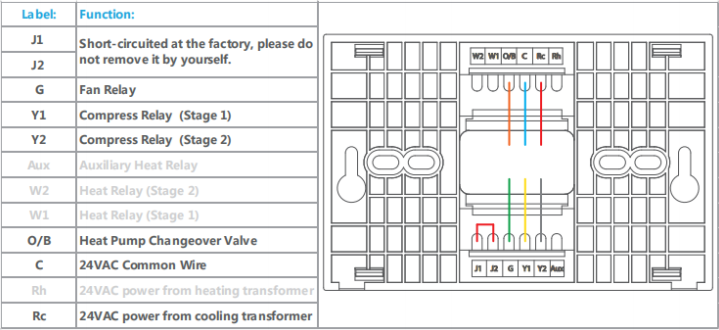
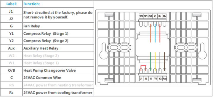
1.If there is one power at your home, please connect C and Rc in the upper right corner as the wirings. And ignore J1 and J2 which has been short-circuited at the factory in the lower left corner.
2.If there are two powers at your home, please connect C, Rc and Rh in the upper right corner. And disconnect J1 and J2 in the lower left corner.
3.If there is no C wire at your home, please run a new cable from the furnace to your thermostat before installation.
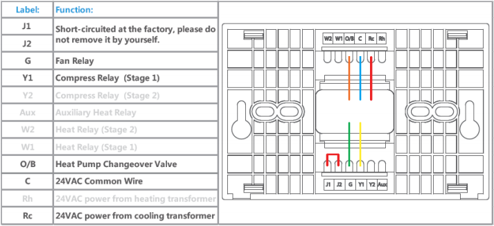

Notes
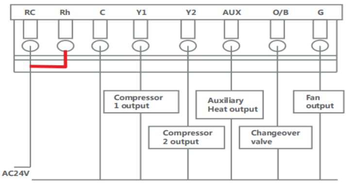
You can connect C and Rh in the upper right corner as the wirings for power.
And ignore J1 and J2 which has been short-circuited at the factory in the lower left corner.


9. Certification
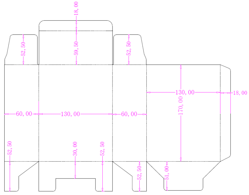
10. Package
